
Data-center cabling
A planned, testable path to every rack and portCarrier, distribution, and equipment areas connect through managed copper and fiber patch fields with planned topology, density, polarity, labels, and tests.
What Data-center cabling includes
Data-center cabling combines topology and administration with physical media. Main, horizontal, intermediate and equipment distribution areas can provide structured transition points appropriate to the facility scale.
Fiber type, connector format, polarity and breakouts must follow the planned switch and server interfaces. High density saves space only when technicians can still inspect, patch, trace and replace components safely.
Question to answer before designHow will the equipment connect and change without adding improvised direct runs during every refresh?
This service may fit when:
- Direct equipment-to-equipment runs obstruct change
- Port growth exceeds panel or pathway capacity
- A speed migration changes optics, polarity or connector density
- A/B cabling cannot be followed from rack to source
What the system includes
A complete scope covers each part below and the connections between them.
Core/distribution
Primary switching and inter-area connectivity
Structured patch field
Managed cross-connect or interconnect points
Row/rack distribution
Trunks, panels and breakouts serving equipment zones
Equipment link
Final patching to compute, storage or network ports
How site information becomes a tested project
A complete project record connects the conditions found on site, the design decisions made from them, and the tests and closeout documents delivered afterward.
What we confirm before design
- Port count, speed, media and interface by equipment
- Topology, A/B and failure-domain requirements
- Rack elevations and pathway capacity
What those findings determine
- Topology: Use port count, churn, reach and operations method.
- Fiber interface: Plan polarity and migration across every component.
- Copper use: Validate reach, heat, power and interface requirements.
What you should receive
- Physical connectivity and port matrix
- Rack/panel elevation and polarity map
- Labeled trunks, panels and patch fields
The exact inputs, decisions, and acceptance records depend on the site and signed scope.
Project stagesSurvey through closeoutView details
How the work moves from survey to closeout
Each stage should produce the records and test results needed before the next stage begins.
- 01
Port and topology model
Map equipment ports, speeds, media, patch points, A/B relationships and forecast growth.
EvidencePort matrix and logical-to-physical topology - 02
Physical design
Select panels, trunks, polarity, cable lengths, pathways, labels and maintenance access.
EvidenceRack elevations, bill of material basis and polarity map - 03
Stage and install
Prelabel, inspect and place cable systems in sequence with cabinets and network equipment.
EvidenceInstallation/inspection log and end-to-end mapping - 04
Test and reconcile
Run specified media tests, resolve exceptions and align records with live port assignments.
EvidenceTest files, port reconciliation and as-built patch schedule
Design choicesCompare the available approachesView details
How to choose the right approach
The right choice depends on the site, application, operating risk, and acceptance requirements. More equipment does not automatically improve the system.
What we need to know
- Port count, speed, media and interface by equipment
- Topology, A/B and failure-domain requirements
- Rack elevations and pathway capacity
- Connector density, polarity and migration method
- Testing, labeling and change-record standards
What you should receive
- Physical connectivity and port matrix
- Rack/panel elevation and polarity map
- Labeled trunks, panels and patch fields
- Copper/fiber acceptance-test files
- As-built cable and patching schedule
Equipment examplesSee relevant hardwareView details
Hardware that may be part of the project
These examples are not a final bill of materials. We confirm compatibility, availability, and the exact model after the requirements are clear.
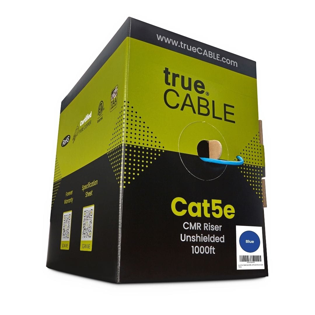
5ECMRBLU_1Kbx
24 AWG solid-copper Cat5e riser cable for 1 and 2.5 Gigabit links up to 328 feet, with PoE++ support
Equipment planning price $260 ↗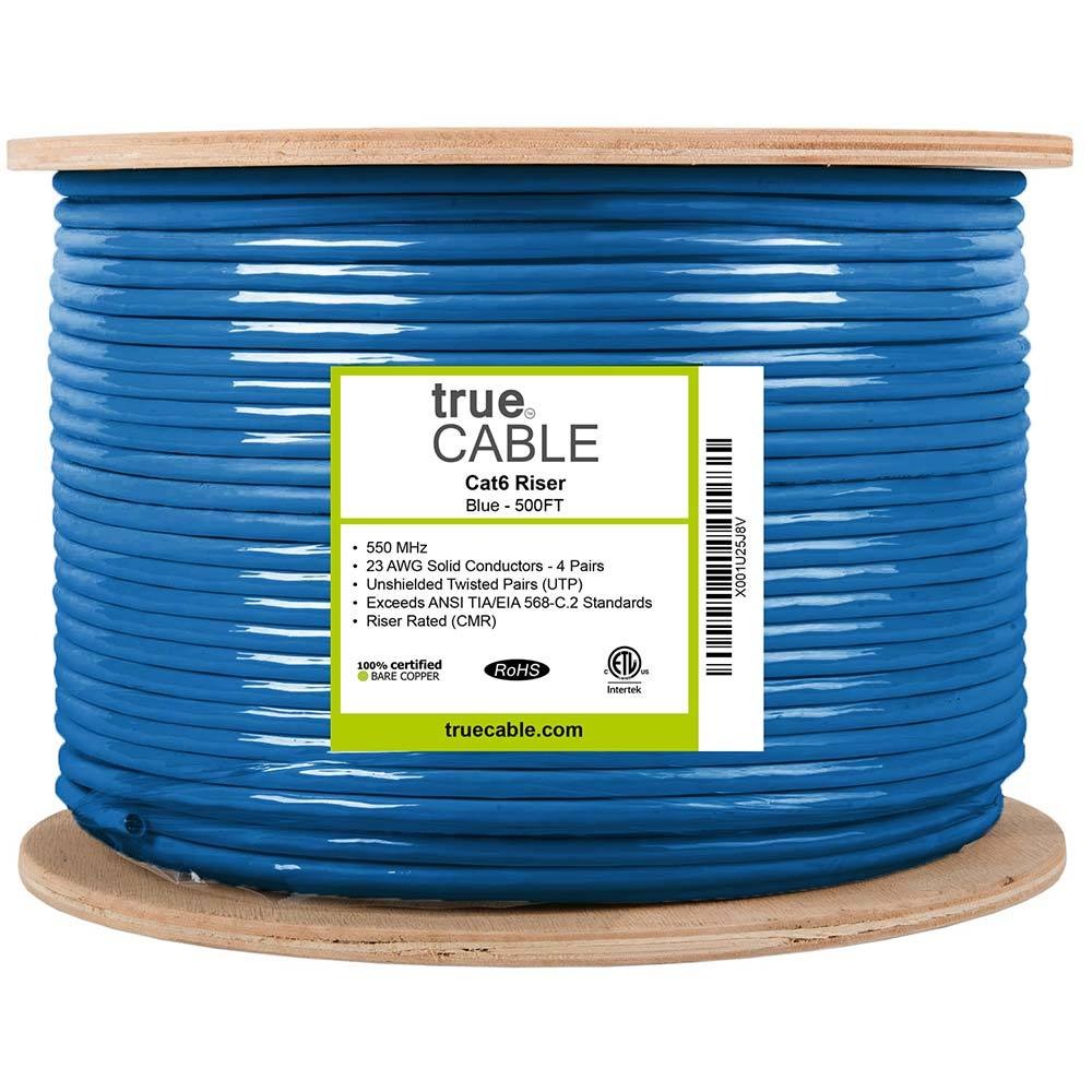
6ECMRBLU
23 AWG solid-copper Cat6 riser cable, terminated, labeled and certification-tested as part of the installed link
Equipment planning price $320 ↗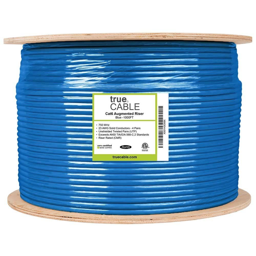
6ACMRBLU
23 AWG solid-copper Cat6A riser cable engineered for 10 Gigabit links up to 100 meters
Equipment planning price $470 ↗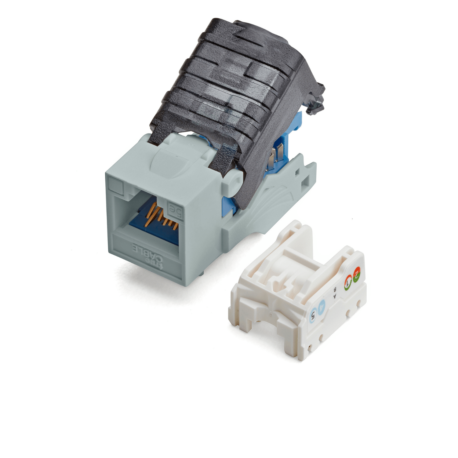
5ETL90CMPTGRY_6pc
Six component-rated Cat5e keystone terminations for work-area outlets and modular patch panels, tested to 250 MHz
Equipment planning price $30 ↗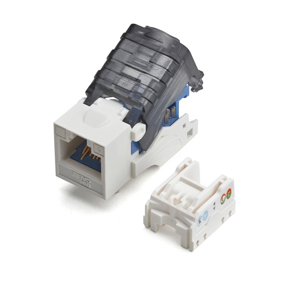
6ETL90CMPTWHT
Component-rated Cat6 keystone termination used at the work-area outlet and patch panel
Equipment planning price $5 ↗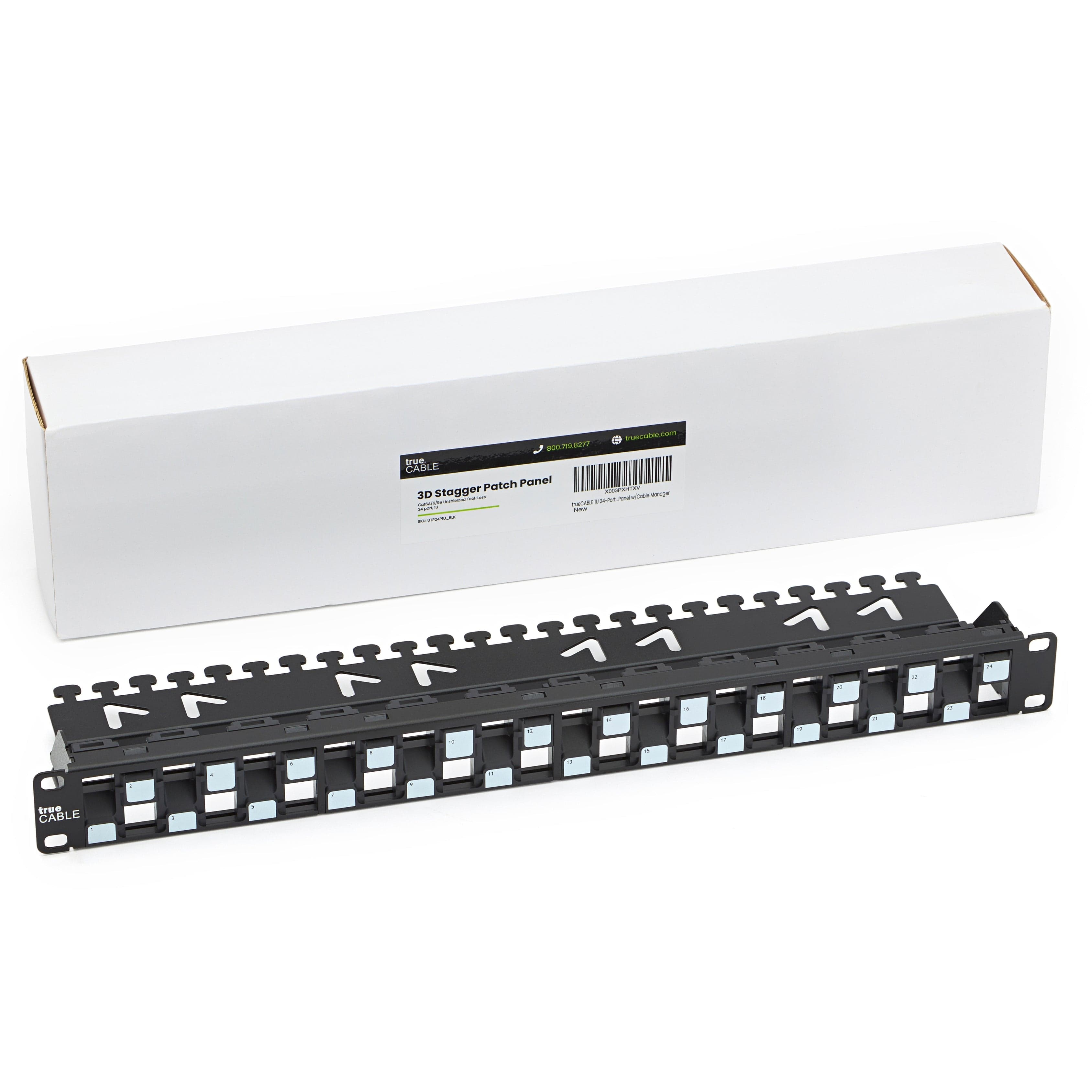
UTP24P1U
1U 24-port modular patch panel for a clean, labeled and serviceable network head-end
Equipment planning price $90 ↗When this service makes sense
- New row or cage connectivity
- Leaf-spine and high-density server environments
- Storage, compute and network refreshes
- Meet-me-room and cross-connect standardization
What we verify first
- Live-equipment access and approved maintenance windows
- Density versus inspection and serviceability
- Polarity and transceiver compatibility
- Pathway separation, airflow and cable-volume limits
Site contextSee where this work is usedView details
How site conditions change the design
Occupancy, operating hours, user activity, regulation, weather, construction, and access can change the design.


What people usually ask
What is a cross-connect?
It is a managed patching arrangement between separate termination fields. It can improve change control at scale but adds components, loss and documentation that must be designed into the link.
Are direct-attach cables part of structured cabling?
They are equipment interconnects rather than permanent balanced or optical building cable plants. They still need port, length, bend, support and change-control planning inside the rack or row.
How is high-density fiber polarity controlled?
By defining one end-to-end method across trunks, cassettes or modules, patch cables and equipment interfaces, then labeling and testing the actual assembled path.
Standards and referencesReview the source materialView details
Sources used for this guide
These references inform the guide. The adopted code, engineer of record, authority having jurisdiction, manufacturer instructions, and signed agreement control the project.
Covers data-center telecommunications infrastructure, topology and related facility coordination.
Open reference ↗Telecommunications Industry Association · reviewed 2026-08-20TIA-568: Commercial Building Telecommunications Cabling StandardsPrimary standards family for generic premises copper and optical-fiber cabling.
Open reference ↗BICSI · reviewed 2026-08-20BICSI Library of ICT Manuals and StandardsOfficial index for ICT installation, outside-plant, WLAN, DAS, data-center and bonding/grounding references.
Open reference ↗IEEE 802.3 Working Group · reviewed 2026-08-20IEEE 802.3 EthernetOfficial working-group source for Ethernet physical-layer and media standards.
Open reference ↗