
Campus and outdoor fiber
High-capacity fiber across campuses, yards, and exposed routesRoute and utility discovery, civil coordination, cable construction, splicing, testing, strand records, and restoration planning, combined into one build.
What Campus and outdoor fiber includes
Outside-plant fiber begins where the cable leaves the protected building environment. Cable construction, water blocking, armor, strength, conduit, handholes, aerial support and building transition must match the route.
The optical design starts with the communications system, distance and loss budget. Fiber count should also account for resilience, restoration and credible growth because civil work usually dominates the difficulty of adding capacity later.
Question to answer before designWhat route, fiber count, topology, and optical loss budget are required, and who owns each civil and property boundary?
This service may fit when:
- Buildings depend on leased or bandwidth-limited links
- Conduit, handhole or route ownership is uncertain
- A new building or exterior system needs backbone connectivity
- Existing fiber lacks strand maps or baseline tests
What the system includes
A complete scope covers each part below and the connections between them.
Building entrance
Transition, protection and termination at each facility
OSP route
Conduit, handholes, direct-buried or aerial support system
Fiber cable plant
Cable, splices, closures, connectors and spare strands
Optical service
Transceivers and applications constrained by distance and loss
How site information becomes a tested project
A complete project record connects the conditions found on site, the design decisions made from them, and the tests and closeout documents delivered afterward.
What we confirm before design
- Endpoint locations, distance and service requirements
- Property, easement, permit and utility information
- Existing conduit, handhole, pole and entrance condition
What those findings determine
- Route method: Use property, utility, environment, access and restoration needs.
- Topology: Physical diversity must be verified, not inferred from a diagram.
- Fiber count: Compare fiber cost with future civil-work cost.
What you should receive
- Route and entrance plan
- Strand, splice and closure schedule
- Calculated and measured loss records
The exact inputs, decisions, and acceptance records depend on the site and signed scope.
Project stagesSurvey through closeoutView details
How the work moves from survey to closeout
Each stage should produce the records and test results needed before the next stage begins.
- 01
Route and utility discovery
Map endpoints, property limits, utilities, civil conditions, permits and access.
EvidenceRoute exhibit, risk register and utility coordination record - 02
Optical design
Select topology, cable construction, fiber count, closures, entries and link-loss budget.
EvidenceStrand plan, component schedule and calculated loss budget - 03
Construct and place
Coordinate civil work, inspect pathway, place cable and protect building transitions.
EvidenceDaily route photos, footage/marker log and installation exceptions - 04
Splice, test and document
Complete splicing, end-to-end testing and route/strand closeout.
EvidenceSplice records, OLTS results, OTDR traces where scoped and as-built map
Design choicesCompare the available approachesView details
How to choose the right approach
The right choice depends on the site, application, operating risk, and acceptance requirements. More equipment does not automatically improve the system.
What we need to know
- Endpoint locations, distance and service requirements
- Property, easement, permit and utility information
- Existing conduit, handhole, pole and entrance condition
- Topology, fiber count and loss budget
- Restoration, outage and future-growth requirements
What you should receive
- Route and entrance plan
- Strand, splice and closure schedule
- Calculated and measured loss records
- Route-marker and closeout photo set
- As-built map and restoration information
When this service makes sense
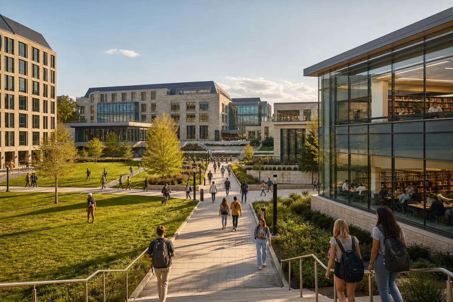
- Education, healthcare and corporate campuses
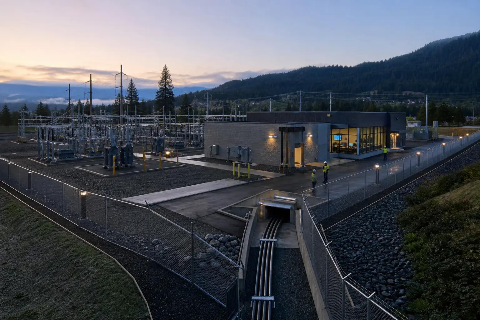
- Manufacturing, utility and logistics sites
- Parking, gate, camera and remote-building links
- Backbone replacement or resilient route projects
What we verify first
- Utility locating, permitting and property rights
- Water, temperature, loading and cable-environment compatibility
- Pulling tension, bend radius and pathway condition
- Civil restoration, weather and controlled work windows
Site contextSee where this work is usedView details
How site conditions change the design
Occupancy, operating hours, user activity, regulation, weather, construction, and access can change the design.

What people usually ask
Why install spare fiber strands?
Additional strands can support restoration, redundancy and planned growth. The decision should compare incremental cable and termination cost with the difficulty of repeating civil work.
Does an OTDR result replace an insertion-loss test?
No. OTDR data is useful for locating and characterizing events; end-to-end insertion loss directly evaluates the cable plant loss seen by the link.
Can two paths shown on a plan be called diverse?
Only after their real routes, entrances, handholes, poles and shared risk points are verified. Diagram separation alone does not establish physical diversity.
Standards and referencesReview the source materialView details
Sources used for this guide
These references inform the guide. The adopted code, engineer of record, authority having jurisdiction, manufacturer instructions, and signed agreement control the project.
Explains requirements discovery, route planning, loss budgets, documentation and restoration planning.
Open reference ↗Fiber Optic Association · reviewed 2026-08-20Outside Plant Fiber Optic InstallationCovers preparation, placement, splicing, testing and documentation for outside-plant fiber.
Open reference ↗Fiber Optic Association · reviewed 2026-08-20FOA-6a: Fiber Optic Cable PlantsDefines cable-plant components, loss-budget comparison, acceptance testing and documentation.
Open reference ↗BICSI · reviewed 2026-08-20BICSI Library of ICT Manuals and StandardsOfficial index for ICT installation, outside-plant, WLAN, DAS, data-center and bonding/grounding references.
Open reference ↗