
Pathways and containment
Protected routes that stay reachable for the next pullTrays, conduit, sleeves, raceway, and supports carry communications cable while accounting for fill, bend radius, separation, firestopping, and access.
What Pathways and containment includes
A pathway may be tray, basket, conduit, sleeves, raceway, J-hooks, underfloor space or a coordinated combination. Containment is selected for cable quantity, media, environment, accessibility and architectural conditions.
Pathway design is also a construction-coordination task. Penetrations, fire-resistance boundaries, structural attachments, ceiling access and trade ownership must be resolved before installation.
Question to answer before designCan every cable reach its destination without overfill, sharp transitions, inaccessible sections, or conflicts with other building systems?
This service may fit when:
- Ceilings are crowded or access is limited
- Existing supports are full, damaged or shared improperly
- A renovation crosses rated walls or occupied areas
- Future phases need reserved route capacity
What the system includes
A complete scope covers each part below and the connections between them.
Origin
Telecom room, entrance facility or equipment zone
Primary pathway
Tray, conduit or route carrying the main cable group
Transition
Sleeve, pull point, drop-out or change in pathway method
Destination support
Final protected route to the outlet, device or enclosure
How site information becomes a tested project
A complete project record connects the conditions found on site, the design decisions made from them, and the tests and closeout documents delivered afterward.
What we confirm before design
- Scaled route and ceiling information
- Cable types, counts and outside diameters
- Fire-rated and security boundaries
What those findings determine
- Accessibility: Consider future changes, not only first-install appearance.
- Cable volume: Size each segment from cable geometry and allowed fill.
- Environment: Match pathway, hardware and cable rating to actual exposure.
What you should receive
- Annotated route plan
- Pathway segment and penetration schedule
- Coordination/responsibility notes
The exact inputs, decisions, and acceptance records depend on the site and signed scope.
Project stagesSurvey through closeoutView details
How the work moves from survey to closeout
Each stage should produce the records and test results needed before the next stage begins.
- 01
Route survey
Trace origin, destination, obstacles, ratings, access and existing pathway condition.
EvidenceAnnotated route plan and obstruction photos - 02
Capacity design
Estimate media count, size, bend needs, pulling access and growth allowance by segment.
EvidenceSegment schedule with pathway type and capacity basis - 03
Trade coordination
Resolve attachment, penetration, firestop, lift, shutdown and restoration responsibilities.
EvidenceCoordination notes and responsibility matrix - 04
Install and inspect
Verify support spacing, transitions, protection, identification and restored barriers.
EvidenceInspection record, route photos and updated as-built
Design choicesCompare the available approachesView details
How to choose the right approach
The right choice depends on the site, application, operating risk, and acceptance requirements. More equipment does not automatically improve the system.
What we need to know
- Scaled route and ceiling information
- Cable types, counts and outside diameters
- Fire-rated and security boundaries
- Structural attachment and trade constraints
- Known future phases and growth allowance
What you should receive
- Annotated route plan
- Pathway segment and penetration schedule
- Coordination/responsibility notes
- Installation inspection record
- Closeout photos and as-built route
When this service makes sense
- New construction and major renovation
- High-density wireless, camera or workstation programs
- Hospitals, schools and industrial environments with restricted routes
- Remediation of unsupported or inaccessible cable
What we verify first
- Pathway capacity and cable handling limits
- Fire-resistance and penetration restoration
- Structural attachment and seismic requirements where applicable
- Shared-ceiling congestion and safe access
Site contextSee where this work is usedView details
How site conditions change the design
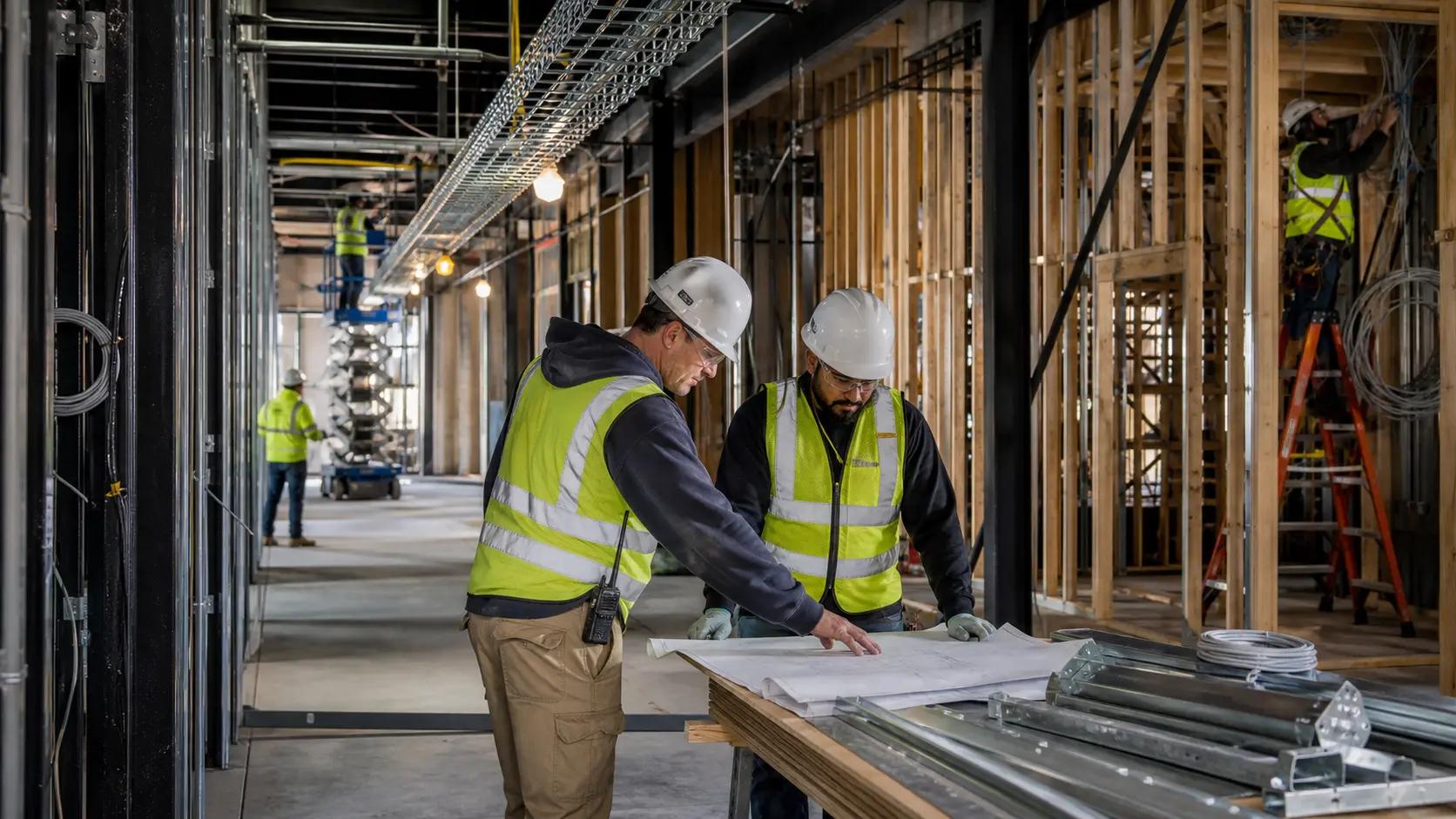
Occupancy, operating hours, user activity, regulation, weather, construction, and access can change the design.


What people usually ask
Is an open ceiling a pathway?
Open space alone does not define a support system. The design still needs an approved route, independent supports, protected transitions and coordination with building conditions.
How much spare pathway should be included?
There is no universal percentage for every project. Use known phases, cable geometry, permitted fill, pulling conditions and the owner’s realistic change pattern.
Who handles firestopping?
That must be assigned in the project documents. The responsible party, approved system, inspection evidence and restoration of existing penetrations should be explicit before work starts.
Standards and referencesReview the source materialView details
Sources used for this guide
These references inform the guide. The adopted code, engineer of record, authority having jurisdiction, manufacturer instructions, and signed agreement control the project.
Defines the telecommunications pathway and space requirements that inform route and room planning.
Open reference ↗Telecommunications Industry Association · reviewed 2026-08-20TR-42 Telecommunications Cabling SystemsOfficial committee index for premises cabling, administration, optical fiber, pathways, bonding and grounding work.
Open reference ↗BICSI · reviewed 2026-08-20Telecommunications Distribution Methods ManualICT design reference spanning spaces, backbone and horizontal distribution, testing, outside plant and data centers.
Open reference ↗