
Structured cabling
Every outlet labeled, every link tested, every record accurateCopper or fiber links, outlets, patch panels, pathways, and labels for computers, Wi-Fi, cameras, phones, and building systems.
What Structured cabling includes
Structured cabling is the standards-based permanent infrastructure between equipment rooms and outlets. It includes the cable, connectors, patch panels, outlets, pathways, labels and records, not just the cable itself.
Media and category are selected from application speed, distance, environment, pathway, power delivery and useful-life requirements. A higher category is not automatically the better design when another medium or topology fits the requirement more directly.
Question to answer before designHow many devices need service, what must each link support, and what route and test standard apply?
This service may fit when:
- Unlabeled or abandoned cabling obscures active links
- New devices exceed available ports or pathway capacity
- Moves and remodels require repeatable outlet standards
- Link errors point to possible physical-layer faults
What the system includes
A complete scope covers each part below and the connections between them.
Work area
Outlet or service point where the device connects
Horizontal link
Permanent copper or fiber segment through the approved pathway
Telecom room
Labeled patching, rack space, bonding and power coordination
Network edge
Switch port, policy and powered-device budget serving the link
How site information becomes a tested project
A complete project record connects the conditions found on site, the design decisions made from them, and the tests and closeout documents delivered afterward.
What we confirm before design
- Floor plan and device locations
- Application speeds and power-over-Ethernet loads
- Cable distances and environmental conditions
What those findings determine
- Typical use: Start with application, distance and lifecycle, not category name alone.
- Acceptance: Define the required test and result format in the scope.
- Administration: Choose the record depth the support team will maintain.
What you should receive
- Outlet and cable schedule
- Labeled patch-panel and work-area terminations
- Per-link test-result files
The exact inputs, decisions, and acceptance records depend on the site and signed scope.
Project stagesSurvey through closeoutView details
How the work moves from survey to closeout
Each stage should produce the records and test results needed before the next stage begins.
- 01
Requirements
Map devices, applications, distances, density, power needs and owner standards.
EvidenceOutlet schedule, media basis and assumptions register - 02
Route and label plan
Coordinate rooms, pathways, identifiers, patching and future capacity before placement.
EvidenceCable schedule, pathway notes and label convention - 03
Install and terminate
Place cable within handling limits, terminate the permanent link and dress both ends for service.
EvidenceProgress photos and endpoint-to-panel mapping - 04
Test and hand off
Test to the agreed link requirement, resolve exceptions and assemble the final record.
EvidencePer-link test files, exception log, photos and as-built schedule
Design choicesCompare the available approachesView details
How to choose the right approach
The right choice depends on the site, application, operating risk, and acceptance requirements. More equipment does not automatically improve the system.
What we need to know
- Floor plan and device locations
- Application speeds and power-over-Ethernet loads
- Cable distances and environmental conditions
- Room, pathway and ceiling access
- Owner labeling and test-report requirements
What you should receive
- Outlet and cable schedule
- Labeled patch-panel and work-area terminations
- Per-link test-result files
- As-built route and endpoint records
- Exception and remediation log
Equipment examplesSee relevant hardwareView details
Hardware that may be part of the project
These examples are not a final bill of materials. We confirm compatibility, availability, and the exact model after the requirements are clear.
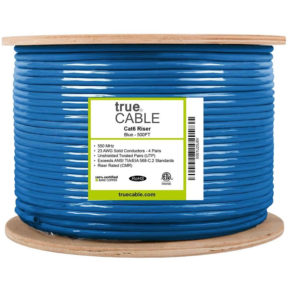
6ECMRBLU
23 AWG solid-copper Cat6 riser cable, terminated, labeled and certification-tested as part of the installed link
Equipment planning price $320 ↗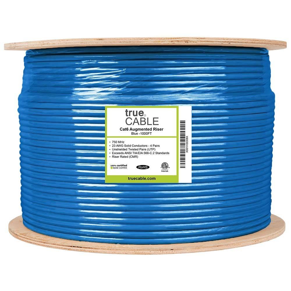
6ACMRBLU
23 AWG solid-copper Cat6A riser cable engineered for 10 Gigabit links up to 100 meters
Equipment planning price $470 ↗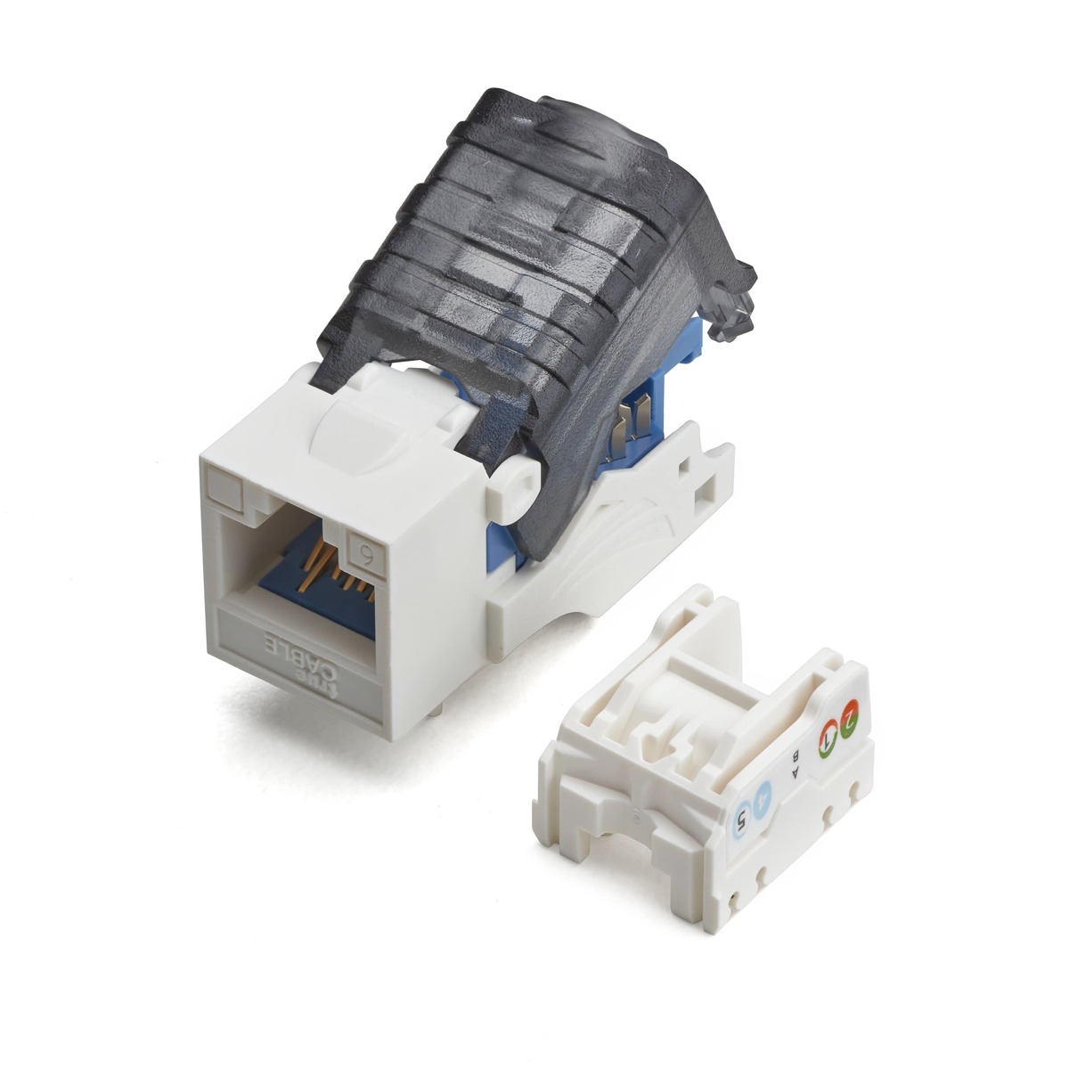
6ETL90CMPTWHT
Component-rated Cat6 keystone termination used at the work-area outlet and patch panel
Equipment planning price $5 ↗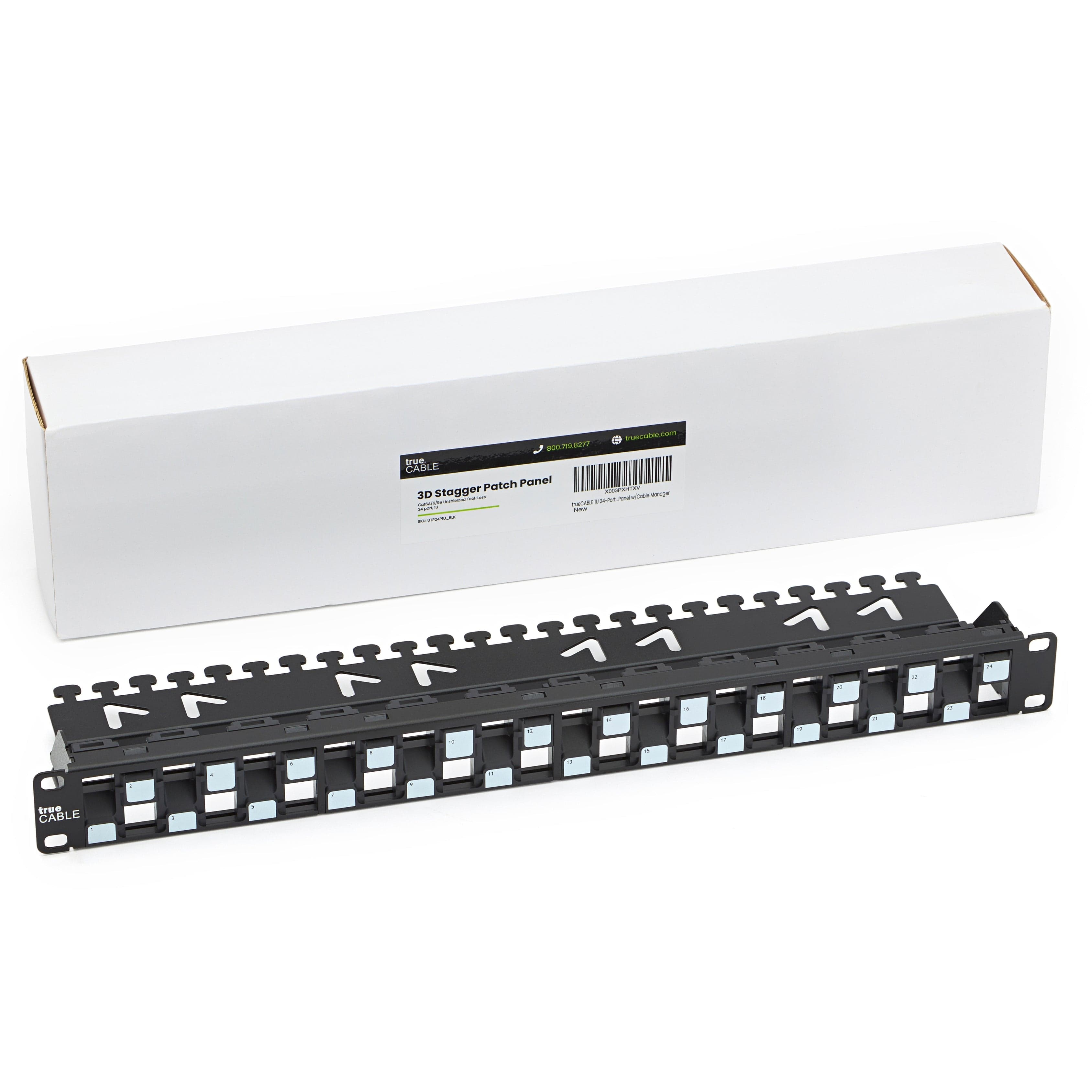
UTP24P1U
1U 24-port modular patch panel for a clean, labeled and serviceable network head-end
Equipment planning price $90 ↗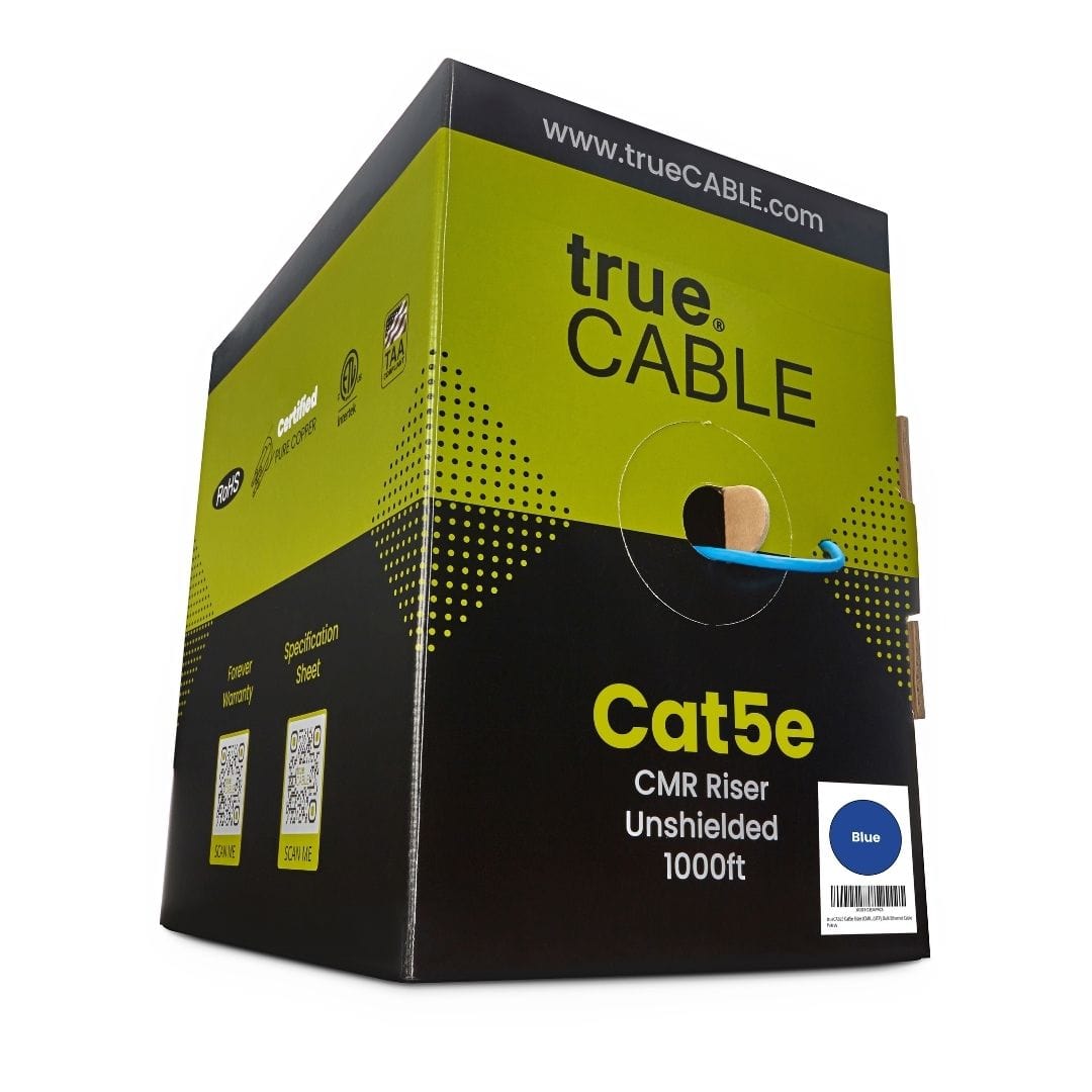
5ECMRBLU_1Kbx
24 AWG solid-copper Cat5e riser cable for 1 and 2.5 Gigabit links up to 328 feet, with PoE++ support
Equipment planning price $260 ↗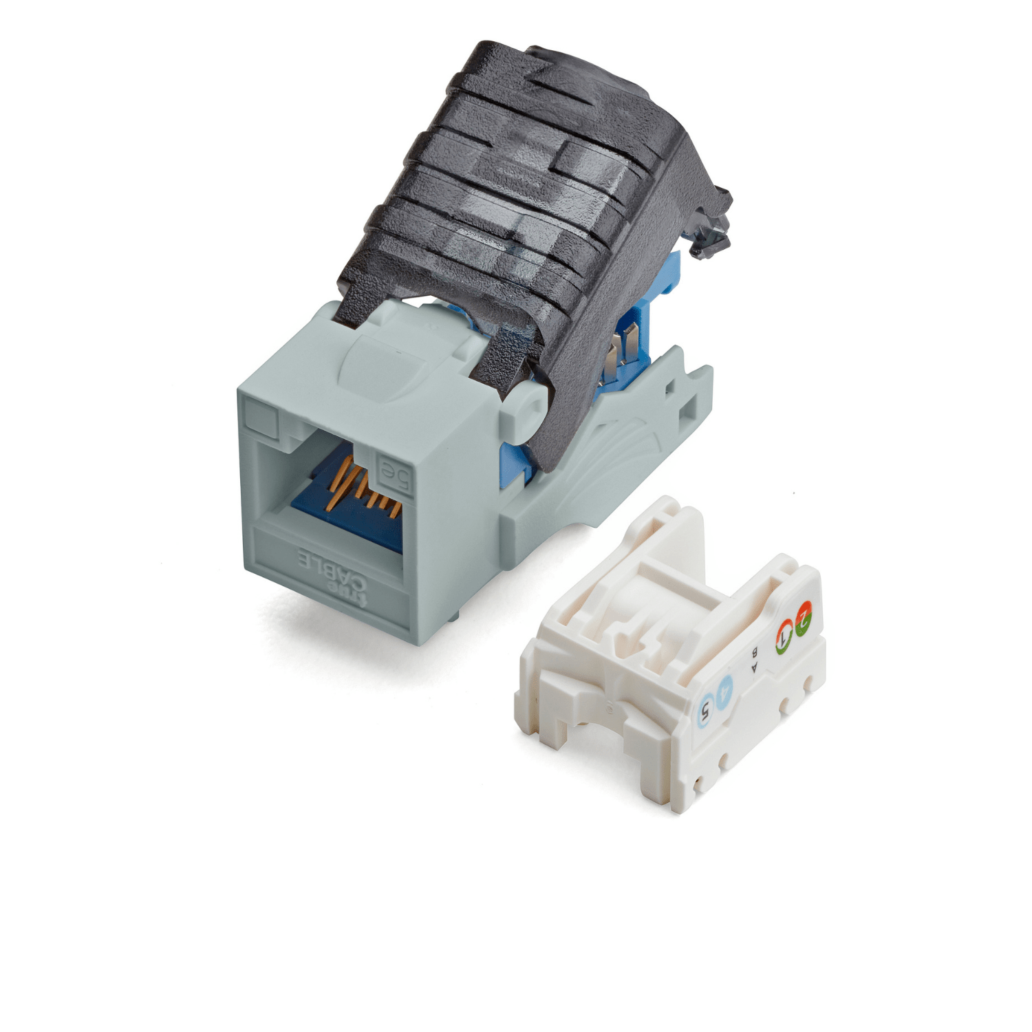
5ETL90CMPTGRY_6pc
Six component-rated Cat5e keystone terminations for work-area outlets and modular patch panels, tested to 250 MHz
Equipment planning price $30 ↗When this service makes sense
- Office, retail, education and healthcare fit-outs
- Multi-site standards and refresh programs
- New wireless, camera, voice or building-system deployments
- Remediation where reliable link records do not exist
What we verify first
- Distance and channel-component limits
- Pathway fill, bend radius and pulling tension
- Separation and coordination with other building systems
- Access windows, occupied-space protection and firestop responsibility
Site contextSee where this work is usedView details
How site conditions change the design
Occupancy, operating hours, user activity, regulation, weather, construction, and access can change the design.



What people usually ask
Is Cat6A always the right choice?
No. The intended application, channel length, bundle and pathway conditions, device power, environment, cost and expected service life should drive the choice.
What does a cable test prove?
That depends on the instrument and limit selected. A certification result can evaluate a permanent link against defined performance limits; a basic continuity test cannot establish the same thing.
What should the owner receive at closeout?
At minimum: a cable and port schedule, durable labels, the agreed test files, as-built location information, photos where useful and a resolved exception list.
Standards and referencesReview the source materialView details
Sources used for this guide
These references inform the guide. The adopted code, engineer of record, authority having jurisdiction, manufacturer instructions, and signed agreement control the project.
Primary standards family for generic premises copper and optical-fiber cabling.
Open reference ↗Telecommunications Industry Association · reviewed 2026-08-20TIA-569: Telecommunications Pathways and SpacesDefines the telecommunications pathway and space requirements that inform route and room planning.
Open reference ↗BICSI · reviewed 2026-08-20Telecommunications Distribution Methods ManualICT design reference spanning spaces, backbone and horizontal distribution, testing, outside plant and data centers.
Open reference ↗IEEE 802.3 Working Group · reviewed 2026-08-20IEEE 802.3 EthernetOfficial working-group source for Ethernet physical-layer and media standards.
Open reference ↗